Energy Calculator Monitors Cooling and Heating Energy, Interfaces With Wide Variety of Instruments

heat energy calculator operator interface
Model 212 Energy Calculator
Courtesy Yokogawa
Early in my professional career, I was a sales rep calling upon building engineers, maintenance technicians, and lots of HVAC related people. One encounter I had, many years ago, has always stayed with me. I was prattling on to a building engineer about whatever gear I was trying to promote for his chilled water system, and I must have really missed the mark. The engineer, clearly a man of superior experience to mine, stopped me in mid sentence. "You know what flows through these pipes?", he said, referring to the chilled water system. In my defense, I was very young and inexperienced at the time, but I did answer "Chilled water". My building engineer friend bellowed out, "Wrong....money flows through those pipes". That single encounter had a lasting impact upon how I viewed HVAC systems.

Energy costs for heating or cooling a building can be the single largest line item on the cash outflow summary for an operation. Much effort and expense is put into efforts to maximize energy efficiency and conservation. Monitoring of usage patterns related to the chilled or hot water system can provide useful information for developing new conservation strategies and verifying the impact of any steps taken to reduce consumption.

The Yokogawa Model 212 is an affordable and easy to install and use device that will provide a stream of usage data. A key feature of the Model 212 is its ability to interface with a broad range of flowmeter devices, including vortex and magnetic flowmeters with pulse outputs, positive displacement and inferential water meters, turbine and paddlewheel flowmeters. This flexibility allows the user to select a companion flowmeter that will suit their accuracy, budget, and operational requirements.

The Heat Calculator has four modes of operation to totalize the usage patterns in a manner that best suits the needs of the user. Additionally, the unit can interface with a building management system and includes internal data logging capabilities. Other features are described in the product data sheet I have included below.

Even small chilled and hot water systems can benefit from usage data derived from a monitoring system such as the Yokogawa Model 212. Share your system challenges with a product specialist. Combining your process and system knowledge with their product application expertise will produce effective solutions.


Learn From CSB Case Study: Industrial Plant Heat Exchanger Explosion

two shell and tube heat exchangers in industrial plant
Large shell and tube heat exchangers
Industrial accidents, whether minor or catastrophic, can serve as sources of learning when analyzed and studied. Operators, owners, and technicians involved with industrial chemical operations have a degree of moral, ethical, and legal responsibility to conduct work in a reasonably and predictably safe manner without endangering personnel, property, or the environment. Part of a diligent safety culture should include reviewing industrial accidents at other facilities. There is much to learn from these unfortunate events, even when they happen in an industry that may seem somewhat removed from our own.

The U.S. Chemical Safety Board, or CSB, is an independent federal agency that investigates industrial chemical accidents. Below, find one of their video reenactments and analysis of an explosion that occurred at a Louisiana chemical processing plant in 2013. A portion of the reenactment shows how a few seemingly innocuous oversights can combine with other unrecognized conditions that result in a major conflagration.

Check out the video and sharpen your senses to evaluate potential trouble spots in your own operation.

Frequency Matters For Radar Level Measurement Applications

radar continuous level measurement instrument transmitter 80 GHz
VEGAPULS 64 80 GHz Radar level measurement transmitter,
shown in one of twelve mounting forms
Courtesy VEGA
Level measurement in tanks and vessels of all types and sizes is a common component of liquid processing operations. For continuous monitoring of liquid level, radar based instruments and transmitters are a newer and faster growing technology. Their ability to perform well under a range of conditions that can prove challenging to other technologies, coupled with their non-contact measuring attribute, make radar level transmitters an advantageous choice for many applications.

Radar based instruments operate within specific frequency ranges. The different operating frequencies can have an impact on instrument cost, size, configuration, and application suitability.

Greg Tischler, Product Manager - Radar at VEGA Americas, a leader in level measurement instrumentation, authored a white paper detailing the application advantages of the more recently deployed 80 GHz radar level instruments. The bulk of the article is excerpted below, or you can read the entire white paper.

The excerpt.....

Focus

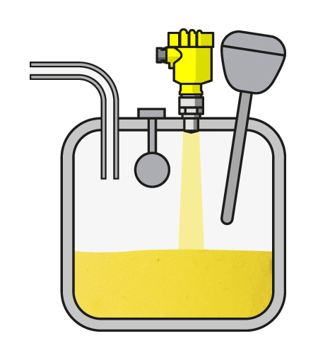
This is the alpha benefit of 80 GHz radar; the one that makes the others possible. In every process, signal focus is crucial to accurate level measurement, and these new instruments emit the most focused signals on the market.
Plant operators have struggled with unfocused radar for decades. The wide beam angle of 26 GHz sensors (and 6 GHz sensors before them) made it difficult for radar signals to miss agitators, heating coils and other vessel internals. The reflections from these installations distorted the echo curve and users were forced to make adjustments to monitor the true liquid level. The new high-transmission models have narrower beams that miss vessel installations—it’s as if they aren’t even there. That is welcome news in chemical and food production, where obtrusive internals are the norm and space is at a premium.
Superior focus makes for accurate measurement without adjustment, but it also opens the door for two other major benefits.
Small process fittings make 80 GHz sensors effective on small tanks.
Small process fittings make 80 GHz
sensors effective on small tanks.
Courtesy VEGA

Size

Because their focus is amped up, 80 GHz sensors have small antennas. The new VEGAPULS 64, for example, has the world’s smallest antenna and doesn’t require a large horn to focus its beam at the measured material. The instrument’s small size makes a huge impact, particularly as it applies to retrofitting. Plants can now integrate the most advanced radar devices into their process without shelling out thousands for modifications to their vessels. Smaller instruments, however, aren’t just good for old vessels; they can also help manufacturers stay nimble and market-responsive.
There’s a trend in the pharmaceutical and chemical industries toward batch production. Batching allows operators to produce seasonal and low-volume products with less financial investment. Small batches are produced in small vessels, where conventional wisdom says using radar is impossible due to small process connections. Thanks to the compact design of 80 GHz radar sensors, that is no longer true, and operators no longer have to sacrifice accurate measurement in the name of space. 

Resolution

Imagine looking at the picture on a standard definition television next to that of an HD TV. The high definition picture would be clearer, sharper, and more detailed due to enhanced resolution. Users will see a similar difference switching from low-frequency to high-frequency radar sensors.
When the level of liquid in a vessel gets low enough, 26 GHz radar reads the echo from the material and the echo from the tank bottom as one echo. This tells the user the vessel is empty when it isn’t and presents a natural handicap to process efficiency. 80 GHz devices measure liquid down to the last millimeter, giving users accurate data they can use to optimize their processes. Greater resolution is particularly important for shipbuilders, who count on precise level in large ballast tanks.
Thanks to Mr. Tischler of VEGA Americas for authoring the white paper excerpted in this article. Share your level measurement challenges with product application specialists, combining your own process knowledge with their product application expertise to develop effective solutions.

Rotary Gas Meters

rotary gas meter roots meter
One example of a rotary gas meter
Courtesy GE - Dresser
Rotary displacement gas meters can be employed across a wide range of applications, from residential through commercial and industrial. Their simple design provides predictable accuracy and long term durability.

A rotary displacement meter is comprised of a pressure containing shell or housing, enclosing two rotating impellers. The impellers have a cross section similar to a figure 8 and rotate in opposing directions within the housing. Gas flows through the chambers created by the rotating impellers. The displacement volume of the rotating impellers is known, so a count of the shaft rotations can be converted into a volumetric flow value. The machining of the housing and impellers is precise and disallows contact among those moving parts. This, of course, contributes to the longevity of the device.

Upstream filtration is advisable to prevent entrance of any foreign particulate matter into the meter which could damage the impeller or housing surfaces. Share your gas metering applications and challenges with a product specialist, combining your facilities and process knowledge with their product application expertise to develop effective solutions.


Limit Switches in Valve Actuators

valve position sensor with limit switches
Valve Position Sensor
Courtesy Westlock Controls
Limit switches are devices which respond to the occurrence of a process condition by changing their contact state. In the industrial control field, their applications and product variations are almost countless. Essentially, the purpose of a limit switch is to serve as a trigger, indicating that some design condition has been achieved. The device provides only an indication of the transition from one condition to another, with no additional information. For example, a limit switch triggered by the opening of a window can only deliver an indication that the window is open, not the degree to which it is open. Most often, the device will have an actuator that is positively activated only by the design condition and mechanically linked to a set of electrical contacts. It is uncommon, but not unknown, for limit switches to be electronic. Some are magnetically actuated, though most are electromechanical. This article will focus on limit switch designs and variants used in the control and actuation of industrial process valves.

Valves, devices used for controlling flow, are motion based. The movable portions of valve trim create some degree of obstruction to media flow, providing regulation of the passage of the media through the valve. It is the movement of critical valve trim elements that limit switches are used to indicate or control. The movable valve trim elements commonly connect to a shaft or other linkage extending to the exterior of the valve body. Mounting electric, hydraulic, or pneumatic actuators to the shaft or linkage provides the operator a means to drive the mechanical connection, changing the orientation or position of the valve trim and regulating the media flow. Because of its positive connection to the valve trim, the position of the shaft or linkage is analogous to the trim position and can be used to indicate what is commonly referred to as “valve position”. Limit switches are easily applied to the valve shaft or linkage in a manner that can provide information or direct functional response to certain changes in valve position.

In industrial valve terms, a limit switch is a device containing one or more magnetic or electrical switches, operated by the rotational or linear movement of the valve.
What are basic informational elements that can be relayed to the control system by limit switches? Operators of an industrial process, for reasons of efficiency, safety, or coordination with other process steps, may need answers to the following basic questions about a process control valve:
  • Is the valve open? 
  • Is the valve closed? 
  • Is the valve opening position greater than “X”? 
  • Has the valve actuator properly positioned the valve at or beyond a certain position? 
  • Has the valve actuator driven the valve mechanism beyond its normal travel limits? 
  • Is the actuator functioning or failing? 
Partial or complete answers to these and other questions, in the form of electrical signals relayed by the limit switch, can serve as confirmation that a control system command has been executed. Such a confirmation signal can be used to trigger the start of the next action in a sequence of process steps or any of countless other useful monitoring and control operations.

Applying limit switches to industrial valve applications should include consideration of:
  • Information Points – Determine what indications are necessary or useful for the effective control and monitoring of valve operation. What, as an actual or virtual operator, do you want to know about the real time operational status of a valve that is remotely located. Schedule the information points in operational terms, not electrical switch terms. 
  • Contacts – Plan and layout a schedule of logical switches that will provide the information the operator needs. You may not need a separate switch for each information point. In some cases, it may be possible to derive needed information by using logical combinations of switches utilized for other discrete functions. 
  • Environment – Accommodate the local conditions and hazards where the switch is installed with a properly rated enclosure. 
  • Signal – The switch rating for current and voltage must meet or exceed those of the signal being transmitted. 
  • Duty Cycle – The cycling frequency must be considered when specifying the type of switch employed. Every switch design has a limited cycle life. Make sure your selection matches the intended operating frequency for the process. 
  • Auxiliary Outputs – These are additional contact sets that share the actuation of the primary switch. They are used to transmit additional signals with specifications differing from the primary signal. 
  • Other Actuator Accessories – Limit switches are often integrated into an accessory unit with other actuator accessories, most of which are related to valve position. A visual local indication of valve position is a common example. 
Switches and indicators of valve position can usually be provided as part of a complete valve actuation package, provided by the valve manufacturer or a third party. It is recommended that spare contacts be put in place for future use, as incorporating additional contacts as part of the original actuation package incurs comparatively little additional cost.

Employing a properly configured valve automation package, with limit switches delivering valve status or position information to your control system, can yield operational and safety benefits for the life of the unit. Good advice is to consult with a valve automation specialist for effective recommendations on configuring your valve automation accessories to maximize the level of information and control.

Severe Service Valve Applications

industrial valve for severe service
Industrial valve for severe service
Industrial process control applications can be associated with some very stringent and challenging performance requirements for the physical equipment and components that are part of the process chain. In fluid based operations, the control and shutoff valves can be a significant impact point of extreme fluid conditions, requiring careful design and selection consideration to assure proper performance and safety levels are predictably maintained.

Industrial valves that are intended for application at the extremes are generally referred to as severe service valves. While there are plenty of published and accepted standards for industrial valves, one does not exist to precisely define a severe service valve. There is, however, some movement toward the development of severe service standards in some industry segments.

So, how do you know when to focus valve selection activities on severe service valves, as opposed to general purpose valves? There are a number of basic criteria that might point you in that direction:

  • Very extreme media or environmental temperature
  • High pressure drop operation that may cause cavitation
  • Rapid and extreme changes to inlet pressure
  • Certain types or amounts of solids contained in the fluid
  • High number of mechanical operations
  • Thermal cycling

Certainly, any of these criteria might be found in an application serviceable by a general purpose valve, but their presence should be an indicator that a closer assessment of the fluid conditions and commensurate valve requirements is in order. The key element for a process stakeholder is to recognize when conditions are in evidence that might overrun the capabilities of a general purpose valve, leading to premature failure in control performance or catastrophic failure that produces an unsafe condition. Once the possibility of a severe service condition is identified, a careful analysis of the possible operating conditions will reveal the performance requirements for the valve.

There are numerous manufacturers of severe service valves, each seeming to concentrate on a particular niche. The oil and gas industry presents numerous applications for specially designed valves, as do other industries.

You can always get more information, or discuss your special requirements, with a product application specialist. They have access to technical resources that can help with selecting the right valve configuration to meet your severe service applications.

Pressure Regulator Valve or Back Pressure Regulator - Appropriate Application

pressure regulating valve pressure regulator
One of many available configurations
for a pressure regulating valve.
Courtesy Cash Valve
Fluids move throughout processes, driven by pressure produced with mechanical or naturally occurring means. In many cases the pressure generated by the driving source is substantially greater than what may be desired at particular process steps. In other cases, the operation may dictate that a minimum pressure be maintained within a portion of the process train. Both cases are handled by the appropriate valve type, designed specifically to regulate pressure.

A pressure regulating valve is a normally open valve that employs mechanical means, positioning itself to maintain the outlet pressure set on the valve. Generally, this type of valve has a spring that provides a countervailing force to the inlet pressure on the valve mechanism. An adjustment bolt regulates the force produced by the spring upon the mechanism, creating an equilibrium point that provides flow through the valve needed to produce the set outlet pressure. A typical application for a pressure regulator is to reduce upstream or inlet pressure to a level appropriate for downstream processing equipment.

Back pressure valves are normally closed, operating in a logically reversed fashion to pressure regulators. Where pressure regulators control outlet pressure, a back pressure valve is intended to maintain inlet pressure. Similar internals are present in the back pressure valve, with the valve action reversed when compared to a pressure regulator. An inlet pressure reduction in the back pressure valve will cause the valve to begin closing, restricting flow and increasing the inlet pressure. A representative application for a back pressure valve is a multi-port spray station. The back pressure valve will work to maintain a constant setpoint pressure to all the spray nozzles, regardless of how many may be open at a particular time.

Both of these valve types are available in an extensive array of sizes, capacities, pressure ranges, and materials of construction to accommodate every process requirement. Share your fluid control challenges with a process control specialist. Combining your process knowledge with their product application expertise will produce effective solutions.