Methods of Continuous Level Measurement in Industrial Process Control

Fuel tanks at refinery
Information about liquid level in a tank is an integral part
of successful process operation and safety.
Many industrial processes require the accurate measurement of fluid or solid (powder, granule, etc.) height within a vessel. Some process vessels hold a stratified combination of fluids, naturally separated into different layers by virtue of differing densities, where the height of the interface point between liquid layers is of interest.

A wide variety of technologies exist to measure the level of substances in a vessel, each exploiting a different principle of physics. This chapter explores the major level-measurement technologies in current use.

Level gauges

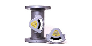
Level gauges are perhaps the simplest indicating instrument for liquid level in a vessel. They are often found in industrial level-measurement applications, even when another level-measuring instrument is present, to serve as a direct indicator for an operator to monitor in case there is doubt about the accuracy of the other instrument.

Float

Perhaps the simplest form of solid or liquid level measurement is with a float: a device that rides on the surface of the fluid or solid within the storage vessel. The float itself must be of substantially lesser density than the substance of interest, and it must not corrode or otherwise react with the substance.

Hydrostatic pressure

A vertical column of fluid generates a pressure at the bottom of the column owing to the action of gravity on that fluid. The greater the vertical height of the fluid, the greater the pressure, all other factors being equal. This principle allows us to infer the level (height) of liquid in a vessel by pressure measurement.

Displacement

Displacer level instruments exploit Archimedes’ Principle to detect liquid level by continuously measuring the weight of an object (called the displacer) immersed in the process liquid. As liquid level increases, the displacer experiences a greater buoyant force, making it appear lighter to the sensing instrument, which interprets the loss of weight as an increase in level and transmits a proportional output signal.

Echo

A completely different way of measuring liquid level in vessels is to bounce a traveling wave off the surface of the liquid – typically from a location at the top of the vessel – using the time-of-flight for the waves as an indicator of distance, and therefore an indicator of liquid height inside the vessel. Echo-based level instruments enjoy the distinct advantage of immunity to changes in liquid density, a factor crucial to the accurate calibration of hydrostatic and displacement level instruments. In this regard, they are quite comparable with float-based level measurement systems. Liquid-liquid interfaces may also be measured with some types of echo-based level instruments, most commonly guided-wave radar. The single most important factor to the accuracy of any echo-based level instrument is the speed at which the wave travels en route to the liquid surface and back. This wave propagation speed is as fundamental to the accuracy of an echo instrument as liquid density is to the accuracy of a hydrostatic or displacer instrument.

Weight

Weight-based level instruments sense process level in a vessel by directly measuring the weight of the vessel. If the vessel’s empty weight (tare weight) is known, process weight becomes a simple calculation of total weight minus tare weight. Obviously, weight-based level sensors can measure both liquid and solid materials, and they have the benefit of providing inherently linear mass storage measurement. Load cells (strain gauges bonded to a steel element of precisely known modulus) are typically the primary sensing element of choice for detecting vessel weight. As the vessel’s weight changes, the load cells compress or relax on a microscopic scale, causing the strain gauges inside to change resistance. These small changes in electrical resistance become a direct indication of vessel weight.

Capacitance

Capacitive level instruments measure electrical capacitance of a conductive rod inserted vertically into a process vessel. As process level increases, capacitance increases between the rod and the vessel walls, causing the instrument to output a greater signal. Capacitive level probes come in two basic varieties: one for conductive liquids and one for non-conductive liquids. If the liquid in the vessel is conductive, it cannot be used as the dielectric (insulating) medium of a capacitor. Consequently, capacitive level probes designed for conductive liquids are coated with plastic or some other dielectric substance, so the metal probe forms one plate of the capacitor and the conductive liquid forms the other.

Radiation

Certain types of nuclear radiation easily penetrate the walls of industrial vessels, but are attenuated by traveling through the bulk of material stored within those vessels. By placing a radioactive source on one side of the vessel and measuring the radiation reaching the other side of the vessel, an approximate indication of level within that vessel may be obtained. Other types of radiation are scattered by process material in vessels, which means the level of process material may be sensed by sending radiation into the vessel through one wall and measuring back-scattered radiation returning through the same wall.

Laser

Lasers can be employed essentially as distance measuring instruments, emitting a beam from above the target material and measuring the elapsed time for the emission to return as a reflection from its surface. With no moving parts, this can be an attractive technology for some applications.

The sales and application engineers at Classic Controls are experts in industrial level control. Feel free to contact them with your level measurement and control challenges. Combine your own process knowledge and experience with their product application expertise to develop an effective solution.
Match Temperature Sensor Configuration to the Application for Best Results

heat tracing temperature sensor
Special construction features can better adapt a temperature
sensor to measuring process conditions.
Image courtesy Pyromation
There are more temperature controlled operations than any of us could count in a lifetime, each with a set of signature performance requirements and design challenges. Matching the means of temperature measurement, the control loop characteristics, and heat delivery method to the application are essential to achieving successful operation.

Step one is to measure the process temperature. This sounds simple until you start researching products and technologies for measuring temperature. Like the temperature controlled operations mentioned previously, they are numerous. To filter the possible candidates for temperature sensing devices, consider these aspects of your application and how well a particular sensor may fulfill your requirement.
  • Response Time - How rapidly the sensor will detect a change in process temperature is a function of how the sensor is constructed and how it is installed. Most temperature sensors are enclosed or encapsulated to provide protection for the somewhat vulnerable sensing element. Greater mass surrounding the sensing element, or a shape that inhibits heat transfer from the process to the sensor, will slow sensor response. Whether the slower response time will adversely impact process operation needs to be considered. More consideration is due to the manner in which the temperature sensor assembly is installed. Not all applications involve a fluid in which the sensor assembly can be conveniently immersed, and even these applications benefit from careful sensor placement.
  • Accuracy - Know what your process needs to be effective. Greater levels of accuracy will generally cost more, possibly require more care and attention to assure the accuracy is maintained. Accuracy is mostly related to the type of sensor, be it RTD, thermocouple, or another type.
  • Sensitivity - Related to the construction, installation, and type of sensor, think of sensitivity as the smallest step change in process temperature that the sensor will reliably report. The needs of the process should dictate the level of sensitivity specified for the temperature sensor assembly.
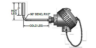
Take a simple application as an illustration. Heat tracing of piping systems is a common function throughout commercial and industrial settings experiencing periods of cold weather. Electric heat trace installations benefit from having some sort of control over the energy input. This control prevents excessive heating of the piping or applying heat when none is required, a substantial energy saving effort. A temperature sensor can be installed beneath the piping's insulation layer, strapped to the pipe outer surface. A specially designed sensor assembly can improve the performance of the sensor and the entire heat trace control system by enhancing the response time of the temperature sensor. A right angled sheath permits insertion of the sensor beneath the piping insulation while orienting the connection head upright. A surface pad at the tip of the sheath increases the surface contact with the pipe to provide faster sensor response. The surface pad is a metal fixture welded to the sensing end of the temperature sensor assembly. It can be flat, for surface temperature measurements, or angled for installation on a curved surface, like a pipe. The increased surface contact achieved with the surface pad promotes the conduction of heat to the sensor element from the heated pipe in our illustration. This serves to reduce and improve the response time of the sensor. Adding some thermally conductive paste between the pad and the pipe surface can further enhance the performance. While the illustration is simple, the concepts apply across a broad range of potential applications that do not allow immersion of the temperature assembly in a fluid.

A simple modification or addition of an option to a standard sensor assembly can deliver substantially improved measurement results in many cases. Share your temperature measurement requirements and challenges with a process measurement specialist. Leverage your own process knowledge and experience with their product application expertise.

Controller Reduces Standby Cycling to Conserve Energy

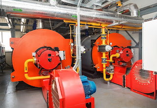
gas fired boilers in boiler room
Improved control can reduce dry firing of boilers,
with substantial energy savings.
Heating of commercial and institutional buildings presents a case where there are energy savings available through the application of an advanced control element able to substantially reduce boiler operation time.

Building owners, boiler engineers, operators and other stakeholders will benefit from this simple and understandable video explanation of some of the inefficiencies associated with boiler operation, and how incorporating an additional control element can minimize boiler dry firing (also called standby cycling). Boiler operation costs can be reduced between 10% and 25%, with a commensurate reduction in carbon footprint, by including the Fireye NXM2G control in the boiler control system.

Watch the video. It's just a few minutes and explains the source of the inefficiency, as well as the solution, in a manner understandable to everyone. More information is available from a combustion product specialist, who can help evaluate the efficiency of your current system or assist with incorporating the latest energy saving features and design into a new installation.

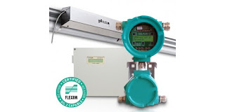
Ultrasonic Clamp-On Flowmeter with SIL 2 Rating

SIL 2 capable clamp on ultrasonic flowmeter
FLUXUS F/G70X and F/G80X series meters
Image Courtesy Flexim
Measuring the flow quantity of gases and liquids is a common industrial processing task. There are numerous technologies available for measuring fluid flow, each with its own set of advantages and drawbacks for any particular application. Some of the technologies and methods have been in use for a very long time, with recent enhancements provided by electronics or smart sensor designs.

Ultrasonic flow measurement devices employ a comparatively recent technology to measure gaseous or liquid flow. Whether the transit time differential or Doppler method is utilized, ultrasonic flow meters have a distinctive characteristic in that they can be deployed in a form factor that does not require contact with the the process fluid, nor insertion in the fluid flow path. A common installation method is to clamp the ultrasonic transducer assembly onto the exterior of a process pipe. This makes the technology attractive for applications that involve adding a flow measurement point to an existing piping system.

Flexim, a globally recognized leader in ultrasonic flow measurement, offers a number of permanent and portable units for measuring liquid and gaseous flow rates. Some of their instruments have been certified as SIL 2 capable, along with a host of other third party certifications. The product range includes simple and accurate instruments designed for general industrial use, and extends to multi-beam units intended for applications, such as custody transfer of fluids, that require the highest accuracy and overall performance levels.

Share your flow measurement challenges and requirements with instrumentation specialists, combining your own process knowledge and experience with their product application expertise to develop effective solutions.


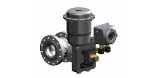
Segmented Ball Rotary Control Valve for Natural Gas Regulation

segmented ball rotary control valve for natural gas
Segmented ball valve for natural gas regulation,
shown with Digital Natural Gas Positioner
Image courtesy GE Becker
The manufacturers of valves and other fluid control components for the processing industries have continuously developed new designs and innovated existing designs to deliver better performance for targeted operating conditions. The available basic valve designs, along with their variants, create an immense catalog of potential candidates for each application.

One such design variant is the segmented ball  valve. It is a quarter turn valve, like its cousin the ball valve, but the trim is different. True to its name, the active closure structure is but a portion of what we know of as a common ball valve. Where the closure mechanism of a ball valve essentially is a solid ball with a hole drilled through it, a segmented ball valve more resembles a section of a sphere or hollowed out ball with a shaped opening in the surface. A primary distinction between the two is that a ball valve contains a passageway through the diameter of the ball that rotates around a central axis. A segmented ball valve functions somewhat more like a gate valve and has no machined pathway through the closure, only a formed surface that restricts a portion of the fluid pathway.

The closure in a ball valve can be floating or trunnion mounted. A segmented ball valve will have a trunnion style mounted closure, with rigid support on opposing points of its diameter. Ball valves, with their rotating fluid pathway resembling a short tube, are generally not the best option for flow control, being better suited for isolation applications. The segmented ball valve functions similar to a sliding gate valve, providing an increasing or decreasing shaped opening as the shaft is turned.

GE Oil & Gas, under the Becker brand name, utilizes segmented ball valves for natural gas regulation applications. There are other industrial applications where this valve type can deliver superior performance and overcome a number of otherwise challenging conditions.

The brochure included below provides more detail on the segmented ball valves targeted for natural gas operations. There are some good illustrations that detail the valve construction. Share your fluid control challenges of all types with valve specialists, leveraging your own process knowledge and experience with their product application expertise to develop an effective solution.

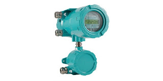
Flexim Wins Recognition for Innovative Flow Measurement

ultrasonic flow meter
Flexim F704 Ultrasonic Flow Meter
Image courtesy Flexim Americas
Flow Control Magazine, which targets solutions for fluid movement, measurement and containment, handed out its annual Innovation Awards recently. Among those receiving honorable mention was Flexim Americas Corporation, for the Fluxus Cryo that provides noninvasive measurement of cryogenic fluids. Special design adaptations prevent ice build up on the measurement apparatus that that can plague other technologies.

Ultrasonic flow measurement offers some distinct advantages over other available methods, with high accuracy, no intrusion into the media, and no moving parts. While the award was specifically for a cryogenic application, Flexim ultrasonic flow measurement instruments are available for an extensive array of applications.

For more information, share your flow measurement requirements and challenges with process instrumentation experts, leveraging your own process knowledge and experience with their product application expertise to develop effective solutions.

Magnetic Flow Meters: Principles and Applications

magnetic flow meter, magmeter, or flowmeter
Magnetic flowmeters are well suited for flow measurement
with conductive fluids.
Image courtesy Yokogawa
Fluid process control operations rely on the operator's ability to accurately determine qualities and quantities of liquid or gaseous materials. In terms of appraising and working with fluids (such as liquids, steam, and gases) the flow meter is a staple tool, with the simple goal of expressing the delivery of a subject fluid in a quantified manner. Measurement of media flow velocity can be used, along with other inputs, to determine volumetric or mass flow. The magnetic flow meter, also called a magmeter, is one of several technologies used to measure fluid flow.

In general, magnetic flow meters are sturdy, reliable devices able to withstand hazardous environments while returning accurate measurements to operators of a wide variety of processes. The magnetic flow meter has no moving parts. The operational principle of the device is powered by Faraday’s Law, a fundamental scientific principle stating that a voltage will be induced across any conductor moving at a right angle through a magnetic field, with the voltage being proportional to the velocity of the conductor. The principle allows for an inherently hard-to-measure quality of a substance to be expressed via the magmeter. In a magmeter application, the meter produces the magnetic field referred to in Faraday’s Law. The conductor is the fluid. The actual measurement of a magnetic flow meter is the induced voltage corresponding to fluid velocity. This can be used to determine volumetric flow and mass flow when combined with other measurements.

The magnetic flow meter technology is not impacted by temperature, pressure, or density of the subject fluid. It is however, necessary to fill the entire cross section of the pipe in order to derive useful volumetric flow measurements. Faraday’s Law relies on conductivity, so the fluid being measured has to be electrically conductive. Many hydrocarbons are not sufficiently conductive for a flow measurement using this method, nor are gases. On the other hand, water and aqueous solutions tend to exhibit sufficient conductivity to apply magmeter technology.

Magmeters apply Faraday’s law by using two charged magnetic coils; fluid passes through the magnetic field produced by the coils. A precise measurement of the voltage generated in the fluid will be proportional to fluid velocity. The relationship between voltage and flow is theoretically a linear expression, yet some outside factors may present barriers and complications in the interaction of the instrument with the subject fluid. These complications include a higher amount of voltage in the liquid being processed, and coupling issues between the signal circuit, power source, and/or connective leads of both an inductive and capacitive nature.

In addition to salient factors such as price, accuracy, ease of use, and the size-scale of the flow meter in relation to the fluid system, there are multiple reasons why magmeters are the unit of choice for certain applications. They are resistant to corrosion, and can provide accurate measurement of dirty fluids – making them suitable for wastewater measurement. As mentioned, there are no moving parts in a magmeter, keeping maintenance to a minimum. Power requirements are also low. Instruments are available in a wide range of configurations, sizes, and construction materials to accommodate various process installation requirements.

As with all process measurement instruments, proper selection, configuration, and installation are the real keys to a successful project. Share your flow measurement challenges of all types with a process measurement specialist, combining your own process knowledge and experience with their product application expertise to develop an effective solution.

Fluid Processes - When A Butterfly Valve Is The Best Choice

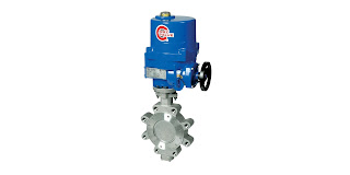
high performance butterfly valve with actuator
High performance butterfly valve with actuator
Image courtesy ABZ Valve
Industrial process control valves are available in uncountable combinations of materials, types, and configurations. An initial step of the selection procedure for a valve application should be choosing the valve type, thus narrowing the selection field to a more manageable level. Valve "types" can generally be classified by the closing mechanism of the valve.

A butterfly valve has a disc that is positioned in the fluid flow path. In the most common form of butterfly valve, the disc rotates around a central axis, the stem, through a 90 degree arc from a position parallel to the flow direction (open) to perpendicular (closed). A variety of materials are used in the valve body construction, and it is common to line the valve with another material to provide special properties accommodating particular process media.

What attributes might make a butterfly valve a beneficial selection over another valve type?
  • The closure arrangement allows for a comparatively small size and weight. This can reduce the cost, space, and support requirements for the valve assembly.
  • Generally low torque requirements for valve operation allow for manual operation, or automation with an array of electric, pneumatic, or hydraulic actuators.
  • Low pressure drop associated with the closure mechanism. The disc in the flow path is generally thin. In the fully open position, the disc presents its narrow edge to the direction of flow.
  • Quarter turn operation allows for fast valve operation.
  • Some throttling capability is provided at partially open positions.
  • Small parts count, low maintenance requirements.
What may be some reasons to consider alternate valve types?
  • Butterfly valve throttling capability is generally limited to low pressure drop applications
  • Cavitation can be a concern.
  • Some sources mention the possibility of choked flow as a concern under certain conditions.
Butterfly valves, like other valve types, have applications where they outperform. Careful consideration and consultation with a valve expert is a first step toward making a good selection. Combine your process know-how with the product application expertise of a professional sales engineer to produce the best solutions to your process control challenges.


Nitrogen Generator Animation Video - Pressure Swing Adsorption


Nitrogen is utilized throughout the industrial and commercial sectors It is incorporated as part of many compounds used to make a wide range of products. Nitrogen is also used as a cooling medium and as a means to isolate flammable or reactive compounds from oxygen.

There are several methods employed to generate or provide nitrogen, each with certain aspects making them advantageous to a certain range of applications. Convenience, reliability of supply, space, cost, energy consumption, purity, and a host of other factors can weigh on the decision for nitrogen supply.

Parker Balston, a globally recognized manufacturer of gas process equipment, employs pressure swing adsorption in some of its nitrogen generating equipment. The video illustrates the process and the brochure included below details the product offering for a wide range of applications. Nitrogen generation on site can provide an effective and economic means of providing a clean nitrogen supply for industrial operations. Share your requirements with product application specialists to see how a nitrogen generator system can benefit your operation.


VigilantPlant Solutions Partner Program

control station for industrial process automation and control
Classic Controls - Authorized Systems Integrator
under Yokogawa VigilantPlant Solutions Partner Program
Image courtesy of Yokogawa  
Classic Controls is one of a very few Authorized Systems Integrators in the Yokogawa VigilantPlant Solutions Partner Program. Extensive and specialized capability is a core requirement of membership. Classic Controls, in addition to their provision of total solutions for process measurement, control, and automation challenges, provides special focus on the Yokogawa CENTUM VP, CENTUM CS 3000 R3, and CENTUM CS control platforms. Classic Controls has the experience, expertise, training, and resources to deliver consultation, installation, and support for these and other Yokogawa process measurement, control and automation products and systems.

Whether considering a new installation, or upgrading in-place systems, share your plans and challenges with process control and automation experts. Leverage your own experience and knowledge with their product application expertise to develop effective solutions.


ASCO Fluid Automation Applications in Power Plants

power plant for electrical generation
ASCO products have applications throughout the power
generation industry.
Here is a partial listing of power generation plant applications where ASCO products provide reliable solutions.

ASCO Solenoid Valves

Ideal for steam, air, or liquid flows. Throughout the power plant, our solenoid valves provide superior service in areas such as SO2 scrubbing, turbine lubrication systems, and igniter burner No. 2 fuel lines to name a few.

Numatics FRLs

Filters, regulators, and lubricators treat air quality and pressure in your plant’s pneumatic system. Apply them to control pressure or meet filtration requirements for your pneumatic equipment. These high-performance products are available in multiple configurations, including electronic regulators.

ASCO Angle-Body Piston Valves

Well suited to replace ball valves in air, water, and steam applications with pipe sizes 2 1/2" or smaller and up to 150 psi. This compact solution reduces cost of ownership, eliminates water ham- mer, and creates tight shutoff in both directions. Available with limit switches, AS-interface®, and DeviceNetTM protocols, Class I, Div. 2 HS Series position indicators, and low power solenoids.

ASCO Dust Collector Valves

ASCO integral or remote pilot valves are especially designed for dust collector applications, combining high flow, long life, and extremely fast opening and closing to produce reliable and economical operation. Valves with quick mount connections eliminate time consuming thread cutting and sealing.

ASCO Pressure Sensors

A range of high-quality sensors with long-life designs and ensured repeatability, these signal when process media reach pressure set points. They play a vital part throughout the entire power generation process.

ASCO Redundant Control System

The ASCO RCS is a redundant pilot valve system that acts as a single 3-way valve. Features include the ability to perform automatic online testing of the redundant solenoid valves, automatic partial stroke testing of the process valve, and online maintenance capabilities. Use this product in high reliability or critical applications. Certified per IEC 61508 Parts 1 and 2 and are SIL 3 capable.

ASCO Solenoid Pilot Valves

Designed to operate at high cycles or for long periods of dormancy, these 3 and 4-way models provide ensured action in demanding applications. Features include, manual operators, high flows, and explosion-proof options. Plus new 0.55 W models are perfect for networks with low power limitations. Brass and stainless steel versions available.

Numatics Cylinders

A large range of high quality Numatics cylinders that can withstand the harsh environment of power generation systems. Whether you are operating a scrubber, bag house, or damper controls, Numatics cylinders are used to open and close large orifices in these systems. Available in 17 bore sizes from 1 1/2" to 24".

Share your application challenges with a product specialist, combining your own process and facilities knowledge and experience with their product application expertise to develop an effective solution.


Training Program for UPS Users


As part of their dedication to delivering power management equipment and systems that help maintain business operation, Ametek Solid State Controls provides a comprehensive training program for customers, to enable them to understand the operation of their equipment and derive the maximum value from its operation. This short video provides a synopsis of the training program and company philosophy that assure customers are empowered by their equipment, not burdened.

Share your power conditioning and backup power requirements with dedicated specialists, leveraging your own knowledge and experience with their product application expertise to develop effective solutions.

Wireless Transmitters In Process Measurement and Control

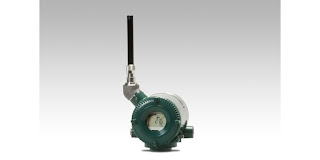
wireless industrial temperature transmitter
Industrial wireless temperature transmitter, one
of many variants available for process measurement
Image courtesy Yokogawa
In process control, various devices produce signals which represent flow, temperature, pressure, and other measurable elements of the process. In delivering the process value from the measurement point to the point of decision, also known as the controller, systems have traditionally relied on wires. More recently, industrial wireless networks have evolved, though point-to-point wireless systems are still available and in use. A common operating protocol today is known as WirelessHARTTM, which features the same hallmarks of control and diagnostics featured in wired systems without any accompanying cables.

Wireless devices and wired devices can co-exist on the same network. The installation costs of wireless networks are decidedly lower than wired networks due to the reduction in labor and materials for the wireless arrangement. Wireless networks are also more efficient than their wired peers in regards to auxiliary measurements, involving measurement of substances at several points. Adding robustness to wireless, self-organizing networks is easy, because when new wireless components are introduced to a network, they can link to the existing network without needing to be reconfigured manually. Gateways can accommodate a large number of devices, allowing a very elastic range for expansion.

In a coal fired plant, plant operators walk a tightrope in monitoring multiple elements of the process. They calibrate limestone feed rates in conjunction with desulfurization systems, using target values determined experientially. A difficult process environment results from elevated slurry temperature, and the associated pH sensors can only last for a limited time under such conditions. Thanks to the expandability of wireless transmitters, the incremental cost is reduced thanks to the flexibility of installing new measurement loops. In regards to maintenance, the status of wireless devices is consistently transmitted alongside the process variable. Fewer manual checks are needed, and preventative measures may be reduced compared to wired networks.

Time Synchronized Mesh Protocol (TSMP) ensures correct timing for individual transmissions, which lets every transmitter’s radio and processor rest between either sending or receiving a transmission. To compensate for the lack of a physical wire, in terms of security, wireless networks are equipped with a combination of authentication, encryption, verification, and key management. The amalgamation of these security practices delivers wireless network security equal to that of a wired system. The multilayered approach, anchored by gateway key-management, presents a defense sequence. Thanks to the advancements in modern field networking technology, interference due to noise from other networks has been minimized to the point of being a rare concern. Even with the rarity, fail-safes are included in WirelessHART™.

All security functions are handled by the network autonomously, meaning manual configuration is unnecessary. In addition to process control environments, power plants will typically use two simultaneous wireless networks. Transmitters allow both safety showers and eyewash stations to trigger an alarm at the point of control when activated. Thanks to reduced cost, and their ease of applicability in environments challenging to wired systems, along with their developed performance and security, wireless industrial connectivity will continue to expand.

Share your connectivity challenges with process measurement specialists, leveraging your own process knowledge and experience with their product application expertise.

Calibration Standards

process instrument field calibrator
Field calibration instruments
Image courtesy of Yokogawa
Calibration is an essential part of keeping process measurement instrumentation delivering reliable and actionable information. All instruments utilized in process control are dependent on variables which translate from input to output. Calibration ensures the instrument is properly detecting and processing the input so that the output accurately represents a process condition. Typically, calibration involves the technician simulating an environmental condition and applying it to the measurement instrument. An input with a known quantity is introduced to the instrument, at which point the technician observes how the instrument responds, comparing instrument output to the known input signal.

Even if instruments are designed to withstand harsh physical conditions and last for long periods of time, routine calibration as defined by manufacturer, industry, and operator standards is necessary to periodically validate measurement performance. Information provided by measurement instruments is used for process control and decision making, so a difference between an instrument’s output signal and the actual process condition can impact process output or facility overall performance and safety.

In all cases, the operation of a measurement instrument should be referenced, or traceable, to a universally recognized and verified measurement standard. Maintaining the reference path between a field instrument and a recognized physical standard requires careful attention to detail and uncompromising adherence to procedure.

Instrument ranging is where a certain range of simulated input conditions are applied to an instrument and verifying that the relationship between input and output stays within a specified tolerance across the entire range of input values. Calibration and ranging differ in that calibration focuses more on whether or not the instrument is sensing the input variable accurately, whereas ranging focuses more on the instrument’s input and output. The difference is important to note because re-ranging and re-calibration are distinct procedures.

In order to calibrate an instrument correctly, a reference point is necessary. In some cases, the reference point can be produced by a portable instrument, allowing in-place calibration of a transmitter or sensor. In other cases, precisely manufactured or engineered standards exist that can be used for bench calibration. Documentation of each operation, verifying that proper procedure was followed and calibration values recorded, should be maintained on file for inspection.

As measurement instruments age, they are more susceptible to declination in stability. Any time maintenance is performed, calibration should be a required step since the calibration parameters are sourced from pre-set calibration data which allows for all the instruments in a system to function as a process control unit.

Typical calibration timetables vary depending on specifics related to equipment and use. Generally, calibration is performed at predetermined time intervals, with notable changes in instrument performance also being a reliable indicator for when an instrument may need a tune-up. A typical type of recalibration regarding the use of analog and smart instruments is the zero and span adjustment, where the zero and span values define the instrument’s specific range. Accuracy at specific input value points may also be included, if deemed significant.

The management of calibration and maintenance operations for process measurement instrumentation is a significant factor in facility and process operation. It can be performed with properly trained and equipped in-house personnel, or with the engagement of subcontractors. Calibration operations can be a significant cost center, with benefits accruing from increases in efficiency gained through the use of better calibration instrumentation that reduces task time.


Rotary and Linear Damper Drives for Control of Combustion Air and Flue Gas

electro-hydraulic damper drive
Electro-hydraulic damper drive, with self contained
pump, power unit, and positioner
Image courtesy of Rexa
Combustion air and flue gas damper drives fill a critical role in the operation of fuel fired equipment, helping to meet safety, regulatory, and efficiency performance criteria with a predictable degree of reliability. It is essential to deploy the best drive technology for each application to maximize combustion efficiency, minimize emissions and reduce installation costs.

Damper Operator (Drives) Types :


Damper drives can be one of three types: pneumatic, electric, or electro-hydraulic.
  • Pneumatic - These damper operators employ compressed air as the motive force when positioning a connected damper.
  • Electric - These operators rely on electric power to operate a drive mechanism, commonly a motor and gear assembly for damper positioning.
  • Electro-hydraulic - Damper operators of this type combine an electrically operated pump that is precisely controlled. The pump moves a hydraulic fluid through a connected mechanism, such as a dual acting piston, to set the damper position.
A very important part of product selection is determination of the damper torque and sizing requirements. Actuator torque should be selected to provide the maximum torque required to operate the damper as well as to provide headroom to compensate for degradation over the life of the damper. Actuators should be evaluated for damper blade movement in both directions, at the beginning of blade movement, and while stroking through the full cycle of movement.

The Goal for Selecting the Best Drive Technology:


Reduced emissions, lower fuel consumption and improved boiler draft control.

Ways to achieve this goal may include drive operating features:
  • High speed continuous modulation 
  • Quick response to plant demand 
  • Reliability in high temperature environments 
  • Precise damper positioning, with no drift once positioned 
  • Simple commissioning and diagnostics 
  • Low operating cost
  • Minimal maintenance burden 
Information on one possible solution is provided below. For more information, share your project requirements and challenges with application specialists, combining your own knowledge and experience with their product application expertise to develop an effective solution.

Product Update: SMARTDAC+ GX/GP Series Recorders & GM Series Data Acquisition System Release 4

data acquisition instruments and equipment
SMARTDAC line of data acquisition instruments
Yokogawa Electric Corporation announced it's Release 4 of the SMARTDAC+® GX series panel-mount type paperless recorder, GP series portable paperless recorder, and GM series data acquisition system.

With this latest release, new modules are provided to expand the range of applications possible with SMARTDAC+ systems and improve user convenience. New functions include sampling intervals as short as 1 millisecond and the control and monitoring of up to 20 loops.

Overview


Recorders and data acquisition systems (data loggers) are used on production lines and at product development facilities in a variety of industries to acquire, display, and record data on temperature, voltage, current, flow rate, pressure, and other variables. Yokogawa offers a wide range of such products, and is one of the world’s top manufacturers of recorders. Since releasing the SMARTDAC+ data acquisition and control system in 2012, Yokogawa has continued to strengthen it by coming out with a variety of recorders and data acquisition devices that meet market needs and comply with industry-specific requirements and standards.

With this release, Yokogawa provides new modules with strengthened functions that meet customer needs for the acquisition and analysis of detailed data from evaluation tests. These modules decrease the cost of introducing a control application by eliminating the need for the purchase of additional equipment.

Enhancements


The functional enhancements available with Release 4 are as follows:

High-speed analog input module for high-speed sampling.


To improve the safety of electric devices such as the rechargeable batteries used in everything from automobiles to mobile devices, evaluation tests must be conducted to acquire and analyze detailed performance data. For this purpose, sampling at intervals as short as 1 millisecond is desirable. However, this normally requires an expensive, high-performance measuring instrument. When the new high-speed analog input module, a SMARTDAC+ system can sample data at intervals as brief as 1 millisecond, which is 1/100th that of any preceding Yokogawa product. This is suitable for such high performance applications such as measurement of the transient current in rechargeable batteries to vibration in power plant turbines. A dual interval function has also been added that enables the SMARTDAC+ to efficiently and simultaneously collect data on slowly changing signals (e.g., temperature) and quickly changing signals (e.g., pressure and vibration).

PID control module for control function


In applications that need both control and recording, such as controlling the temperature of an industrial furnace or the dosage process at a water treatment plant, there is a need for systems that do not require engineering and can be quickly and easily commissioned. In a typical control and monitoring application, a separate recorder and controller is required to control temperature, flow rate and pressure. At the same time, a data acquisition station must communicate with the controller to ensure data is being capture and recorded. It is time consuming and oftentimes confusing, to ensure the controller and the data acquisition station is communicating seamlessly. By combining continuous recording function of the SMARTDAC+ and PID control module into a single platform, customers can now seamlessly control and record critical process data in one system. The SMARTDAC+ can control, monitor and record up to 20 loops. Each PID control module comes with 2 analog inputs, 2 analog outputs, 8 digital inputs and 8 digital outputs.

Four-wire RTD/resistance module for precise temperature measurement


While three-wire RTDs are widely used in many fields such as research institutes to manufacturing, some applications require higher level of precision and accuracy that is only possible with 4-wire RTDs. A 4-wire RTD is the sensor of choice for laboratory applications where accuracy, precision, and repeatability are extremely important. To satisfy this need, Yokogawa has released a 4-wire RTD/resistance module for the SMARTDAC+.

Target Markets


GX series: Production of iron and steel, petrochemicals, chemicals, pulp and paper, foods, pharmaceuticals, and electrical equipment/electronics; water supply and wastewater treatment facilities.

GP series: Development of home appliances, automobiles, semiconductors, and energy-related technologies; universities; research institutes.

GM series: Both of the above target markets.

For more information on the SMARTDAC+ GX/GP Series Recorders & GM Series Data Acquisition System contact Classic Controls at (863) 644-3642 or by visiting http://www.classiccontrols.com.

Dividends From Boiler Combustion Efficiency System

gas fired boilers in machinery room
Fuel fired boiler operation can be costly. Maintaining high
combustion efficiency returns substantial cost savings.
Steam and hot water use is prevalent throughout industrial processes. Production of these two media is most commonly accomplished with a boiler, many of which are heated by combustion of fossil fuel. Fuel fired boilers of a certain size become the focus of regulatory requirements for emissions. All boilers consume what would be construed by their owners as large amounts of costly fuel. Because of their high pressure and temperature, and the presence of a controlled combustion within an occupied facility, safety is a paramount concern.

There, fortunately, is a single solution that can help to attain useful goals with the three concerns of safety, fuel cost, and regulatory compliance. Applying an efficiency controller to manage the fuel to air ratio of the combustion system will deliver benefits far in excess of the cost to incorporate the necessary devices. The three basic goals for the fuel air controller are:
  • Maximize fuel efficiency
  • Minimize regulated emissions
  • Maintain safe operating condition
A good portion of all three goals can be accomplished through careful concerted parallel control of combustion air supply and fuel supply. The fuel air ratio must be subject to continual adjustment in response to current air conditions (which can vary on a daily basis) and the level of O2 in the flue gas. Controlling the air fuel ratio supports the following goals:
  • Preventing excess fuel vapors from entering the flue and creating an unsafe condition
  • Providing the correct amount of air to effectively combust the fuel supplied to the burner
  • Preventing excess air flow from reducing net heat transfer to the feedwater
  • Maintaining regulated emissions within required limits
  • Limiting fuel consumption to the minimum necessary to meet demand
Fireye® is a leading manufacturer of flame safeguard controls and burner management systems for commercial and industrial applications throughout the world. Their products, the first of which was developed in the 1930's, enhance the safety and efficiency of all fuel fired burners.

There are numerous capabilities built in to the company's PPC4000 series of fuel air ratio controllers. Some of the more notable include:
  • Precise fuel air ratio attained using parallel control of servos to regulate fuel and air supplies.
  • User selected burner profiles
  • Alarm contacts
  • PID operation
  • An array of inputs and outputs to accommodate sensors and devices needed to monitor and control boiler operation
  • Compatible with other products that provide additional flame and burner monitoring safety
  • Multiple boiler sequencing and cold start thermal shock protection
  • On board boiler efficiency calculation
  • User interface, optional larger touchscreen interface
Glance through just the first two pages of the document below to get a full description of the capability of this compact and comprehensive controller. You can get more detailed information, or get a professional evaluation of your current system efficiency, by contacting the application experts at Classic Controls.


Laser Spectroscopy Applied to Oxygen Measurement


Combining the analytical function of laser spectroscopy with the simple installation package of an industrial transmitter, the Sick TRANSIC100LP provides direct real time in-process oxygen measurements in a wide range of industrial processes. The short video shows how the unit is easy to install and uncomplicated to operate as part of a process measurement and control system.

Fast results and low maintenance are hallmarks of TRANSIC100LP operation. There are no sample prep requirements and no consumables. Sick explains the operating principle of the transmitter in their technical data sheet...
"The TDLS Tunable Diode Laser Spectroscopy is primarily used in high-end gas analyzers and is characterized by its highly selective measurement capability. The oxygen properties are used for O2 measurement: That means O2 atoms in the near infrared range are stimulated at specific wavelengths. A laser diode modulates the radiation precisely over an absorption peak. The high-energy radiation transfers energy to the O2 atoms and the signals becomes weaker. In the measuring probe, the laser beam hits the O2 atoms and is weakened according to the concentrations of oxygen present there. A receiver measures the intensity of the arriving radiation and accurately determines the absorption. One distinct advantage of laser spectroscopy is it´s insensitivity to possible interference. For O2 in particular, there is no absorption of other gases in the range of sampled absorption peaks."
Watch the video for more detail and some application examples. Share your gas analysis requirements and challenges with process measurement specialists, combining your own process knowledge and experience with their product application expertise to develop effective solutions.

Filled Impulse Lines With Pressure Sensors or Gauges

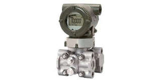
industrial pressure transmitter
Pressure transmitters and gauges are often installed
with impulse lines.
Image courtesy Yokogawa
Pressure sensors intended for use in industrial process measurement and control applications are designed to be robust, dependable, and precise. Sometimes, though, it is necessary or beneficial to incorporate accessories in an installation which augment the performance of pressure sensors in difficult or hazardous environments. There are some scenarios where the sensor must be isolated from the process fluid, such as when the substance is highly corrosive.

A way to aid pressure sensing instruments in situations where direct contact must be avoided is by using a filled impulse line. An impulse line extends from a process pipe of vessel to a pressure measurement instrument or sensor. The line can have a diaphragm barrier that isolates the process fluid from the line, or the line can be open to the process. There are best practices that should be followed in the design and installation of an impulse line to assure that the line provides a useful transmission of the process pressure to the sensor and whatever degree of isolation or protection is needed remains in effect.

The filled impulse line functions via the addition of a non-harmful, neutral fluid to the impulse line. The neutral fluid acts as a barrier and a bridge, allowing the pressure sensing instrument to measure the pressure of the potentially harmful process fluid without direct contact. An example of this technique being employed is adding glycerin as a neutral fluid to an impulse line below a water pipe.

Glycerin’s freeze point is lower than water’s, meaning glycerin can withstand lower temperatures before freezing. The impulse line connected to the water pipe may freeze in process environments where the weather is exceptionally cold, since the impulse line will not be flowing in the same way as the water pipe. Since glycerin has a greater density and a lower freezing point, the glycerin will remain static inside the impulse line and protect the line from hazardous conditions.

The use of an isolating diaphragm negates the need for certain considerations of fill fluid density, piping layout, and the need to create an arrangement that holds the fill fluid in place within the impulse line. System pressure will be transferred across the diaphragm from the process fluid to the fill fluid, then to the pressure sensor. It is important to utilize fluids and piping arrangements that do not affect the accurate transference of the process pressure. Any impact related to the impulse line assembly must be determined, and appropriate calibration offset applied to the pressure sensor reading.

An essential design element of a filled impulse line without an isolating diaphragm is that the fill fluid must be compatible with the process fluid, meaning there can be no chemical reactivity between the two. Additionally, the two fluids should be incapable of mixing no matter how much of each fluid is involved in the combination. Even with isolating diaphragms employed, fluid harmony should still be considered because a diaphragm could potentially loose its seal. If such a break were to occur, the fluids used in filled impulse lines may contact the process fluid, with an impact that should be clearly understood through a careful evaluation.

Share your pressure measurement requirements and challenges with experienced application specialists, combining your own process knowledge and experience with their technical expertise to develop an effective solution.

Digital Valve Positioner

digital valve positioners mounted on linear and rotary valves
D3 digital positioner is suitable for linear or rotary valves
Image courtesy of  Flowserve - PMV
A digital positioner is primarily intended for use with modulating control valves. Full featured units will accommodate single or double acting actuators, as well as rotary and linear valves. A digital positioner is a precision instrument and should be treated with a commensurate amount of care to prevent damage during installation and setup.

The positioner will read a control signal input, such as 4-20 mA. The internal processing of the digital positioner will regulate the operation of air supply and venting valves integral to the positioner, regulating the motive pressure on the actuator and the resulting valve trim position. Positional feedback of the valve position is provided by a potentionmeter.

Units can be provided with one of several different communications options to enable setup and diagnostic information to be transmitted across a network. Good air supply quality and pressure will assure the best positioner performance. Various spindle and bracket arrangements are available to facilitate proper mounting of the digital positioner to the valve actuator.

The use of a digital positioner enables superior modulating valve control and repeatability, along with improved diagnostic information. More detail is contained in the document provided below. Share your fluid control challenges with valve automation experts, combining your own process knowledge and experience with their product application expertise to develop effective solutions.


Thermal Mass Flow Meters for Combustion Efficiency Control and Monitoring

thermal mass flow meter inline style
Example of inline thermal mass flow meter
Image Courtesy Fox Thermal Instruments
Fox Thermal Instruments, a recognized leader in the manufacture of thermal mass flow meters, has authored a white paper entitled "Reduce Energy Costs and Enhance Emissions Monitoring Systems" which provides a technical view of how the use of thermal mass flow measuring technology can be effectively employed on combustion based systems to provide efficient energy usage. Combustion efficiency contributes to the financial benefit of an operation, as well as enabling compliance with emission requirements.

Thermal mass flow measurement is a well regarded mature technology in industrial process measurement and control applications. The instrument returns a mass flow reading by measuring the heat dissipating effect of the media flow on a temperature sensor. Heat transfer is proportional to the mass flow.

The mass flow measurement instruments are very popular for several reasons. They have no moving parts, have a fairly unobstructed flow path, are accurate over a wide range of flow rates, calculate mass flow rather than volume, measure flow in large or small piping systems, and do not need temperature or pressure compensation.

The white paper is provided below for you to read. It is informative and will prove a good investment of time to read. Share your flow measurement challenges of all types with process instrumentation specialists, combining your own process knowledge and experience with their product application expertise to develop effective solutions.


Thoughts on Upside of Outsourcing Industrial Project Work

liquid metering system for pipeline
Many companies that use these liquid metering systems possess
some of the technical and physical resources to design and build
their own. Outsourcing the work can bring the best resources to bear
on the project and free in-house personnel for other tasks.
Photo courtesy Sagebrush Pipeline Equipment
Industrial process measurement and control entails projects, lots of projects. Equipment and instruments that are the life of our processes periodically need modification, replacement, major service or maintenance. Large scale work is generally contracted out for a variety of reasons, not the least of which is that the manpower, equipment, or license and certification requirements are beyond what the stakeholder (the company) may possess . But on smaller projects, an organization is often confronted with the decision of whether to do the work in house or contract it out. There are potential perils and rewards, regardless of the path you take.

The title of this article reveals my leanings on the issue of whether to outsource. Based upon my own project experience and observations of others in their pursuit of project completion, I am generally in favor of it.

Prior to determining whether to use internal or external resources, take the time to document some elemental project requirements.
  • What is the starting condition of the project? It is important to systematically assess the existing conditions, as they have a substantive impact on the scope of work needed to be accomplished to reach the point of completion.
  • What is to be the ending condition of the project, the definition of completion? There must be a defined ending condition that, once achieved, signals that the project is complete. Start with a general statement and add details garnered from various stakeholders. Keep in mind that the end condition will need to satisfy all stakeholders, so their input should be influential.
  • How much time is allowed to complete the work? This pertains to the needs of the company, not the time required to accomplish the task. If there is a deadline for the project, it must be known. An example would be completion of combustion efficiency upgrades prior to the effective date for a new emissions standard. It's not when the work can be done, but when it must be done
  • How much time will be required to complete the work? This may be difficult to ascertain at project inception, but some allowance should be assigned to planning, equipment and material procurement, actual hands-on trade and technical work, startup, testing, commissioning, and final documentation and training. This exercise will help you develop a more detailed picture of what is involved in getting the project completed and how long the timeline might be.
  • What special trade or technical skills will be required? You may need skilled or certified individuals to perform certain tasks. It is essential to know the extent of these resource requirements.
  • Does any of the work require a license or permit? Some extents of modification may require permits from a local jurisdiction and/or licensed trades to perform the work. New work often requires permits. Every jurisdiction has its own set of standards and requirements which must be considered.
Recall that I said document the project requirements. This is important for everyone involved. You want to prevent the drifting of performance benchmarks during the course of the project. This should be especially important if you are the one responsible for project completion. Injections of additional requirements midstream have the potential to destroy your carefully considered plans and result in delays, increased cost, compromised quality, and dissatisfied stakeholders. If somebody wants a change, insist that they be realistic about its impact on the schedule and budget.

There are three major decision factors to consider for in-house or outsourced projects.
  • Technical resources: Do you have people on staff with skills and qualifications that match those that will be needed to accomplish all the tasks comprising the project? That may include substantially more than the mechanics needed to install newly acquired parts and equipment. Consider engineering and design, the production of required documentation, procurement and scheduling of materials and equipment, proactive scheduling and coordination of the various tasks, and general project management.
  • Special equipment and tools: Are there any particular tools, instruments, or equipment that will be required on the project? Does the organization have these resources on hand? If not, how will they be procured, how long does it take, how much does it cost?
  • Available manpower: Are there enough personnel in the organization with the needed skills to complete the work AND is there enough slack available in their schedule to allow a sufficient amount of their time to be devoted to the project to achieve a timely completion? This is critical and applies to both the skilled trade labor and administrative manpower requirements.
An honest and thoughtful consideration of the three areas outlined will likely convince you that, unless the project is small in scale and simple in scope, outsourcing to a contractor with expertise and experience in the work to be accomplished is your best course of action. Sure, dealing with contractors can be difficult and merely outsourcing will not be a panacea for all the challenges presented by any project. However, if a contractor's fulfillment of the three considerations outlined above are better than yours, there is probably advantage in hiring them.

In the big picture, outsourcing can keep your company's resources available to perform tasks more directly related to revenue generation, which is what they were likely hired for in the first place. Outsourcing draws comparatively little from the organization resource pool and, candidly, puts the bulk of the performance burden and the associated aggravation and stress on another organization that is probably better equipped to handled it than you. Done right, it can be a big win for everyone.

Share your process and fluid control projects with experienced professionals and seek out opportunities to be more effective.

Flow Measurement - Sometimes the Simple Solution is Best

variable area flow meter measures and indicates fluid flow directly
These variable area flow meters also permit visible
inspection of flowing media
Courtesy ERDCO Engineering Corp.
For process control and commercial or industrial applications, there are numerous methods of flow measurement from which to choose. Technologies range from very simple applications of physical principles to deployment of very specialized electronics and sensors. The available range of accuracy, response, and cost is quite broad, with a general expectation that higher cost will deliver better performance and accuracy.

Making the best instrument selection for a flow measurement application should include an assessment of what the operators really need in order to safely and effectively run the process or perform the task related to the measurement of fluid flow. Installing instrumentation with capabilities far beyond what is required is almost certainly a waste of financial resources, but may also have an unexpected impact on operators. Through the generation of data that, while accurate, does not provide any actionable information about process condition, operators can be misled, similar to the occurrence of a false or nuisance alarm. Some applications call for high accuracy, some do not. Define your informational needs and select instruments that will meet those needs.

There is a large array of applications that can be satisfied with simpler, less costly measurement technology. These devices often employ turbines or vanes to produce an indication of flow rate. Incorporated into some of the instruments is a means to visually observe the flowing liquid to verify color and clarity. Simple devices sometimes are intended only to indicate the presence of fluid flow, and whether the flow rate is high or low. Configurations are available that allow insertion into lines under pressure (hot tap) through a full port ball valve. Other variants with combinations of features and capabilities abound.

The selection range is enormous, so define your minimum needs first, then search for a compatible product. Your search can be enhanced by contacting an instrumentation specialist. Combining your process expertise with their broad product knowledge will produce effective solutions.